Blog
A Loco visits Kevland: Repairing a locomotive
Assessing the Locomotive’s Initial Fault
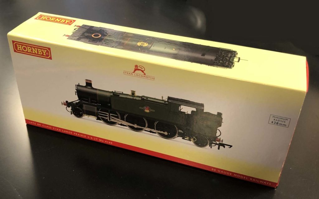
A Hornby Large Prairie 2-6-2T locomotive came into the workshop.
Picture 1
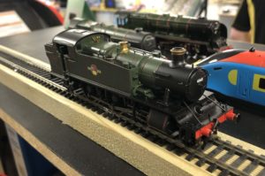
The fault was described as starting then stopping and a buzzing sound.
Once taken apart it is then a case of putting direct power to the motor terminals to check the motor does actually run and it is also a good time to check the running gear, the so called conrods and valve gear to see if they are damaged causing a lock up to happen.
Picture 2
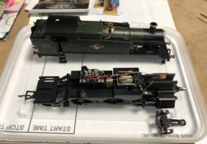
Locomotive Motor and Running Gear Inspection
Tested the motor and all was fine. During this test I did experience a lock up of the wheels whereby they would not turn either way and the cause turned out to be one of the little hexagonal screws that secures the connecting rod onto the wheel. This was not tight enough allowing the very end of the rod to become misaligned. A quick fix was simply to tighten this up with the special Loco Crankpin Box Spanner as shown in this picture.
Picture 3
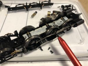
So lock up now fixed, motor runs perfectly but when placed back on the track…same fault is still happening!
Troubleshooting Electrical Contacts and Power Flow
So lets clean all contact wheels which on this particular loco is all of them as each wheel has a copper strip resting on the inside of the wheel behind the flange, taking current to the motor via two wires.
A point of interest here is that this particular Hornby loco, is classed as DCC Ready. It has a plug n play board inside which allows a digital board to be plugged in thus converting it to run on a digital track.
Picture 4
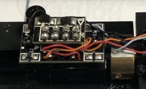
For the time being this can be ignored while I continue to find the initial problem with this loco.
I am now thinking there is a break in the path of the current from track to motor, but a break would normally mean no current at all is getting to the motor where this is getting current to the motor but for only a short period time.
Circuit Board Concerns: Isolating the Issue
I will have to get further inside the model and check the two (very delicate) wires in case there is a trapped wire causing some sort of intermittent connection.
Picture 5
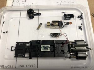
In the picture you can see the motor fitted with a tan coloured smoothing capacitor to the right and the little circuit board for the plug n play digital board between the motor and the remains of the loco chassis.
The red and black wires coming off the circuit board take current from somewhere deep inside the chassis these need to be tested. The orange and grey wires also coming off the circuit board to the motor. These need testing as well.
Picture 6
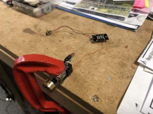
I held the motor with a G clamp so I could touch direct power wires to the four wires at the circuit board. The red and black wires are before the board. These are fine. The orange and grey wires are after the board and these are fine, no breaks anywhere, all four wires work!
The only conclusion now is the circuit board itself!
This board is only in this loco to allow a conversion to digital. It has three surface mounted capacitors. I can now only assume one of these is failing and not giving it’s best performance so current is being starved to the motor after only a few seconds.
Final Assembly and Successful Locomotive Test Run
I can try and get a replacement board from Hornby or remove the board.
I contacted the customer and explained the situation and he said I can go ahead and remove the board as a cheaper option to get his loco back on the track working again.
Picture 7
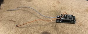
Once the board was out and all the components put back together so it resembles a loco again, I put her on the track and hooray, it works and runs backwards as well as forwards (always check it runs in both directions), so job done.


Should have installed a new mother board .You do not need one from hornby, there are plenty for sale elsewhere. Chip as chips £1.50 p. I got. Few in my spares box which I use when I convert old locos .. Wrenn,,, dublo triang etc into dcc . Try a Bachmann split chassis, they are the hardest..
Thank you for your input, we do appreciate your comment regarding alternative fixes. Kevin